Using 7 segment displays | Usando displays de 7 segmentos - Microcontrollers #6
1 comment
More displays
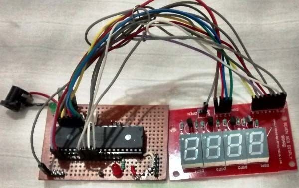
Shoutout to Circuit Digest

In this article you will find:
- Introduction
- What is a 7-segment display?
- Connections
- Setting the code

Greetings to all!
The world of displays is something fascinating where we can find different types such as LCD screens, LED matrices and 7-segment displays.
If you've ever seen an old digital clock, then chances are you've come across 7-segment displays. It is precisely these displays that will be today's topic, where we will learn how to control them and manage their content.
If you want to know how to create counters or simply show figures on a 7-segment display with PIC microcontrollers, just keep reading.

What is a 7-segment display?
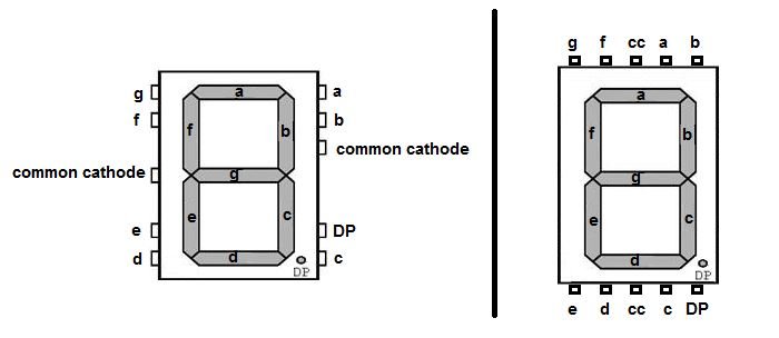
Shoutout to Electronics For You
A 7-segment display is a device that allows us to represent numbers from 0 to 9 or letters, this by means of 7 LED diodes, which are organized in the form of "segments". If we look at the following image:
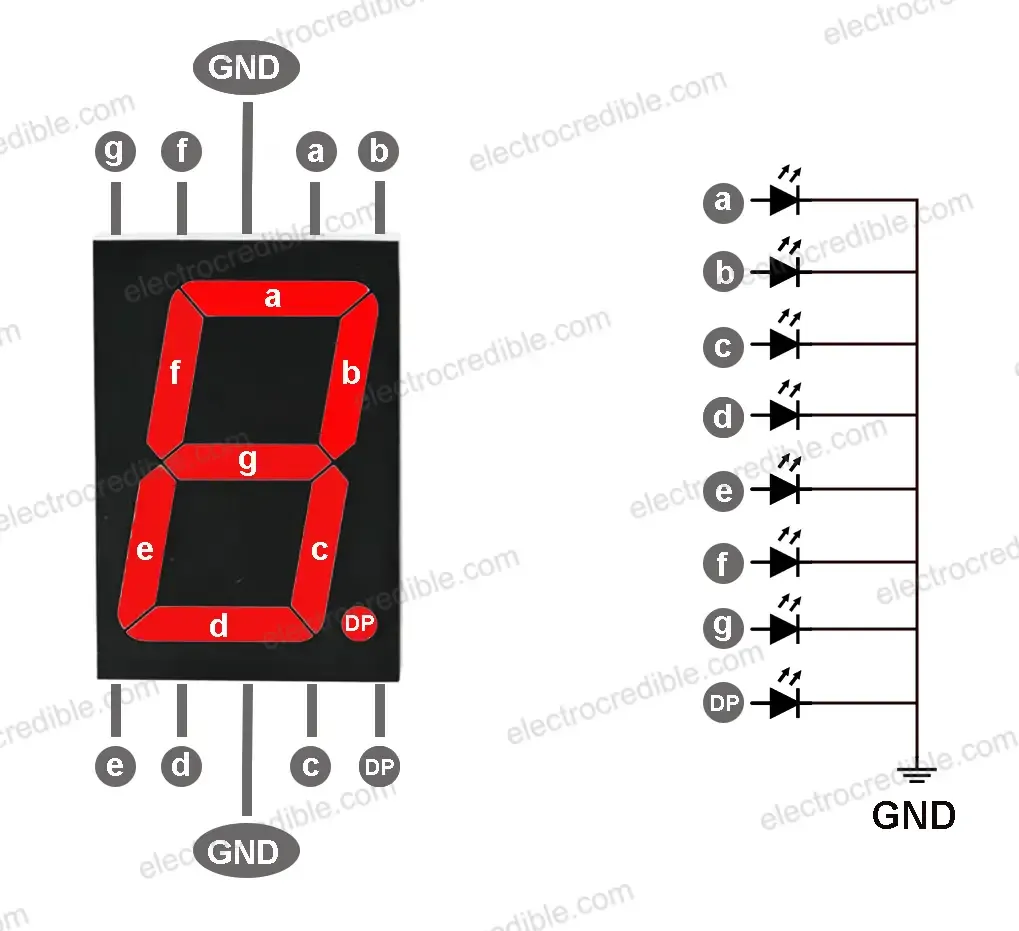
Shoutout to Electrocredible
Here, it is noted that each of these segments or LEDs is designated with a letter, ranging from a to g.
Now, in the case of this type of display, since it is made up of LED diodes, it can have two configurations: Common Anode and Common Cathode.
Remembering that diodes are semiconductor elements that allow the passage of current in one direction (from the anode to the cathode) but not in the other (from the cathode to the anode), then we can describe each configuration as follows:
The Common Cathode, as its name indicates, refers to 7-segment displays where the cathode of the 7 LEDs that compose it are connected to the same point: The earth.
The common anode is the 7-segment display where the anodes of the 7 LEDs are connected to the power supply.
But what do these configurations influence?
If we want to control a 7-segment common cathode display, this will mean that if we want to create a specific number, we will have to power or turn on the corresponding LEDs (For example, b and c for the number 1), while for a display common anode, these bits will need to be set low or grounded.
Once we know this, we can easily discern how we have to create a value within the display. Knowing that 7 segments would be the equivalent of 7 bits, we can then enter a string of bits, where each one, from the least significant, would represent the segments a through g:
For example, if we want to create the number 0 and we look at the image on the display:
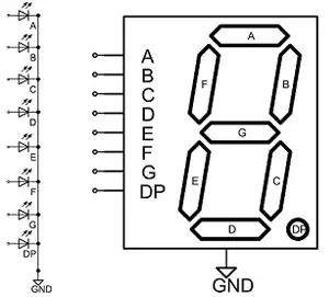
Shoutout to Jameco Electronics
We see that to make this possible, we would have to illuminate LEDs a,b,c,d,e and f, all except g. If this display is a common cathode display then, we would have the following sequence:
0111111
gfedcba
And if it were a common anode, we only invert it to place the bits at 0 (Low).
1000000
gfedcba
If we want to create the number 1, we illuminate b and c:
0000110

or

1111001
And so on, successively until reaching 9, which would be determined by:
1101111
With what we already know how to represent numbers on our display. Let's look at the connections.

Connections
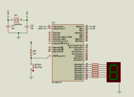
Connecting a 7-segment display is really simple. In this case, since we are using a 7-segment common cathode display, as we can see in the pinout, we will connect the pins D0, D1, D2, D3, D4, D5, D6 and D7 of the PIC16F877A to the pins of a, b, c, d, e, f and g/dp respectively, while we connect the ground pins to the circuit ground. If this were a common anode, the only difference would be that instead of connecting it to ground, we would have Vcc pins that would go to the circuit power.
We must keep in mind that when using voltages of 5V, and that the LED diodes have a recommended voltage lower than this (In this case, 2V for green), we must use resistors to limit the current values to one desirable for these segments (15mA recommended) and thus avoid burning the LEDs.
To calculate what value of resistor we need, we take into account the voltage drop and subtract it from the voltage of our source. Then, we divide this by the current value that the segments require (15mA). If we see the following equation:
R =  (Vcc - Vf)
     ----------
         Io
And when replacing:
R =  (5V - 2V)
     ---------
       15mA

R = 200Ω
With which we can take the commercial value closest to this, which is 220Ω for each resistor associated with the segment.
Thus, we now know the connections and we can move on to the next section: Programming.

Setting the code
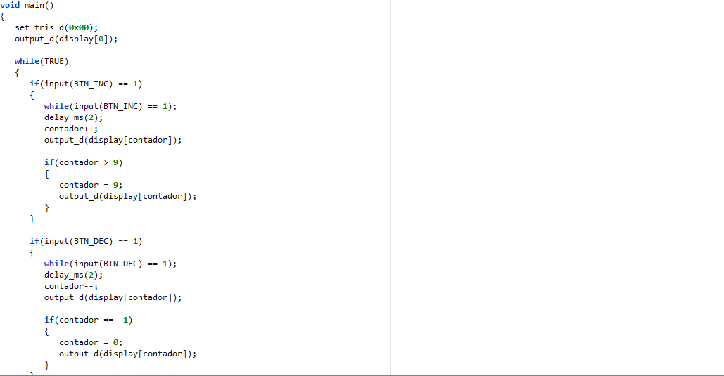
We will start with a program to create a sequence that counts from 0 to 9 on our display and that when it reaches the last number (9), it restarts.
To do this, we must take two things into account:
- We require an element that allows us to store all the values of the numbers (The number 00111111 for 0, 00000110 for 1, etc...).
- We need a variable to increase so that the counter does so as well.
From this, we can infer that the required element will be an array, where we will place all the number sequences. This would look like this:
int display[10] = {0x3F, 0x06, 0x5B, 0x4F, 0x66, 0x6D, 0x7D, 0x07, 0x7F, 0x6F};
Where int symbolizes that all values will be of type integer (which will be translated into binary and allow us to create the sequences). Inside the bracket we place the number of elements and finally, within it, we assign each value.
In this case, we write them as hexadecimal. However, if you want to write it in binary or decimal, you can do that too.
Remembering that in almost every programming language, if we want to access an element of an array, we only have to access a specific index, which will give us the value of the element in that position:
display[0] = 0x3F

display[1] = 0x06

.
.
.

display[9] = 0x6F
In this way, if we want to access each of the elements within the array one at a time, we will have to create a counter, which we can increase to go from one index to another. This is where an int type variable called counter is created.
Now, putting this into program form, we will have:
#include <16f877a.h>
#fuses HS, NOWDT, NOPROTECT, NOPUT, NOLVP, BROWNOUT
#use delay(clock=20M)
#use fast_io(D)

int display[10] = {0x3F, 0x06, 0x5B, 0x4F, 0x66, 0x6D, 0x7D, 0x07, 0x7F, 0x6F};
int counter;

void main()
{
    set_tris_d(0x00);
    output_d(display[0]);

    while(TRUE)
    {
       for(counter = 0; counter < 10 ; counter++)
       {
          output_d(display[counter]);
          delay_ms(200);
       }
    }
}
Where if we analyze the first 4 lines of code, we can see that now, instead of using the standard_io directive, we use fast_io. This is because we do not intend to assign new names to our I/O pins and we only want to place them as input/output as quickly as possible.
Regarding the variables, we can notice our arrangement of values for the display and the counter. Then, within the main we do something very important which is use set_tris_d(), which is an instruction that allows us to place one or more pins of the selected port as inputs (Value 1) and outputs (Value 0).
In this case, since we want all the pins of port D to be outputs, we put 0x00, which would translate to 00000000 as binary. However, if we wanted to place half of the pins as output and the other as input, we would enter the value of 00001111 (D0,D1,D2 and D3 as inputs, D4,D5,D6,D7 as output) and for a single pin as input, only that bit is set to 1.
In addition to this, we ensure that at the beginning of the program, the display always shows us the number 0. We do this through output_d, which is an instruction that sends a value to all the pins of a port. In this case, it will be the one in position 0 of the display array, which will simply be the number 0.
Once inside the while loop, our task will be simple. The simplest way to increment the counter and be able to make the sequence return to 0 when it reaches 9 will be through the use of a for loop, where we will use the counter as the variable to increment.
Here, the counter will start at 0 and will count as long as the value it has is less than 10 in increment rate (Hence the counter < 10 and the counter++).
Finally, once in the for loop, for each execution, with output_d, we will show the display element in the position specified by the counter, which will already be increasing in value. Finally, so that the sequence is not so fast, we place a small delay of 200ms.
Thus, when we run our program, we would have:
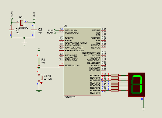
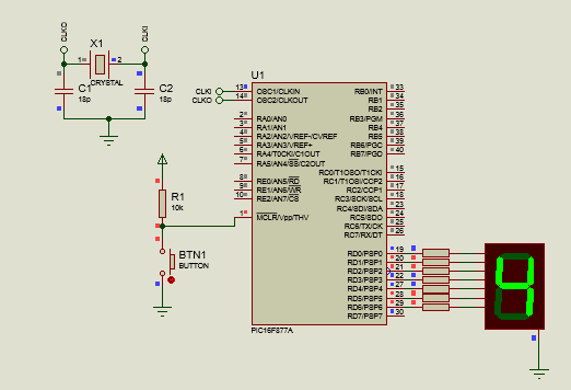
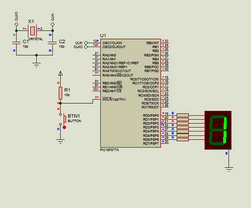
With which we would have a counter that increases automatically. But what happens if we want to manually increase the values of this display?
For this, all you need to do is add a couple of buttons, one to increase and one to decrease, as well as make some adjustments to the code. Viewing the new connection:
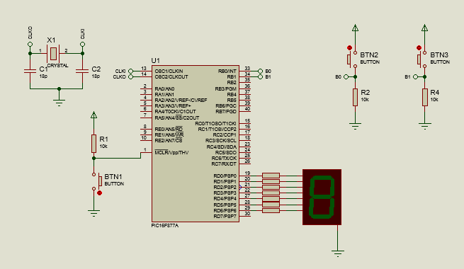
And looking at the new code:
#include <16f877a.h>
#fuses HS, NOWDT, NOPROTECT, NOPUT, NOLVP, BROWNOUT
#use delay(clock=20M)
#use standard_io(B)
#use fast_io(D)

#define BTN_INC PIN_B0
#define BTN_DEC PIN_B1

int display[10] = {0x3F, 0x06, 0x5B, 0x4F, 0x66, 0x6D, 0x7D, 0x07, 0x7F, 0x6F};
int counter;

void main()
{
    set_tris_d(0x00);
    output_d(display[0]);

    while(TRUE)
    {
       if(input(BTN_INC) == 1)
       {
          while(input(BTN_INC) == 1);
          delay_ms(2);
          counter++;
          output_d(display[counter]);

          if(count > 9)
          {
             counter = 9;
             output_d(display[counter]);
          }
       }

       if(input(BTN_DEC) == 1)
       {
          while(input(BTN_DEC) == 1);
          delay_ms(2);
          counter--;
          output_d(display[counter]);

          if(count == -1)
          {
             counter = 0;
             output_d(display[counter]);
          }
       }
    }
}
We can see that the standard_io(B) returns here, since we want to redefine the name of pins B0 and B1 as BTN_INC for the button that will increment the counter and BTN_DEC, the button that will decrement the counter, which we do with the #define directives .
Additionally, within the while loop, we will implement two conditionals:
One to verify if the value of the signal that is input to the increment button pin is high (Hence the input(BTN_INC)), and based on this increment the counter and show the value on the display in the new position of the display arrangement.
Another to verify if the value of the signal for the decrement button is high, which if true, will cause the counter to reduce its value and display the value of the array using the decremented counter as an index.
Note: If you're wondering why we use a while loop and a 2 ms delay even if we know the button has been pressed, we do this to create a debounce, which is simply a small delay that ensures that once the button has been pressed If the button is not pressed, the instructions will be executed, thus preventing the counter from increasing more times than we want.
In addition to this, we place other nested conditionals, which will simply serve to ask us if the counter reached a value greater than 9 or less than 0, which if fulfilled, will cause the counter to return to 9 or 0.
Now, looking at this program running:
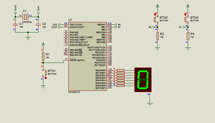
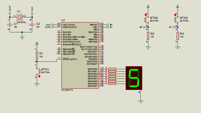
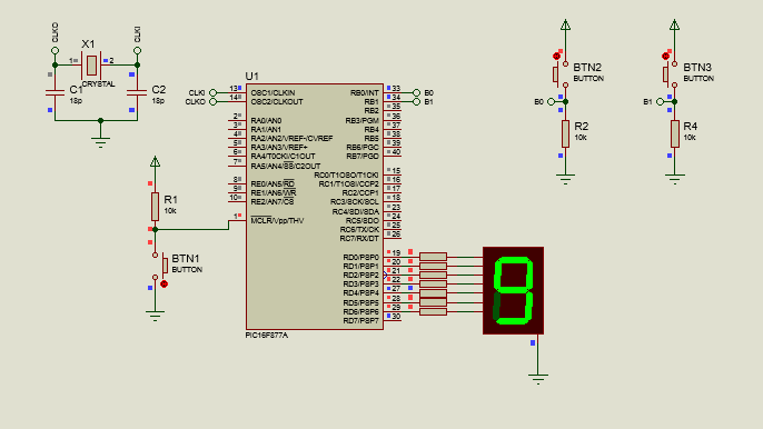
With which we have our counter, showing its value on a 7-segment display.

As you can see, managing the 7-segment display is not complex, especially if you see them as a set of LEDs. In addition to allowing us to show numbers or letters on a display, we can also use more than one display with a single port, which will be the topic of the next article.
I hope this information has been helpful to you if you are looking for a way to show the values of your electronic projects. I encourage you to experiment and stay tuned to this series.
Having said that:


Más displays

Shoutout to Circuit Digest

En este artículo encontrarás:
- Introducción
- ¿Qué es un display de 7 segmentos?
- Conexiones
- Estableciendo el código

¡Un saludo a todos!
El mundo de los displays es algo fascinante donde podemos encontrar distintos tipos como lo son las pantallas LCD, las matrices LED y los displays de 7 segmentos.
Si alguna ves has visto un reloj digital antiguo, entonces es probable que te hayas encontrado con displays de 7 segmentos. Es precisamente estos displays lo que serán el tema de hoy, donde aprenderemos como controlarlos y manejar su contenido.
Si quieres saber como crear contadores o simplemente mostrar figuras en un display de 7 segmentos con microcontroladores PIC, solo tienes que seguir leyendo.

¿Qué es un display de 7 segmentos?

Shoutout to Electronics For You
Un display de 7 segmentos es un dispositivo que nos permite representar números del 0 a 9 o letras, esto por medio de 7 diodos led, los cuales se encuentran organizados en forma de "segmentos". Si observamos la siguiente imagen:

Shoutout to Electrocredible
Aquí, se nota que cada uno de estos segmentos o leds está designado con una letra, que va de la a hasta la g.
Ahora bien, en el caso de este tipo de displays, ya que se encuentra formado por diodos LED, este puede tener dos configuraciones: Ánodo Común y Cátodo Común.
Recordando que los diodos son elementos semiconductores que permiten el paso de corriente en una dirección (Del ánodo al cátodo) más no en la otra (Del cátodo al ánodo), entonces podemos describir cada configuración de la siguiente manera:
El Cátodo Común, como su nombre lo indica, se refiere a los displays de 7 segmentos donde el cátodo de los 7 leds que lo componen se encuentran conectados al mismo punto: La tierra.
El Ánodo común, son los display de 7 segmentos donde los ánodos de los 7 LEDs se encuentran conectados a la alimentación.
Pero ¿En qué influyen estas configuraciones?
Si queremos controlar un display de 7 segmentos de cátodo común, esto significará que si queremos crear un número en específico, tendremos que alimentar o poner en alto a los leds correspondientes (Por ejemplo, b y c para el número 1), mientras que para un display de ánodo común, se tendrá que colocar en bajo o poner a tierra a estos bits.
Una vez que sabemos esto, podemos discernir facilmente como tenemos que crear un valor dentro del display. Sabiendo que 7 segmentos serían el equivalente a 7 bits, entonces podemos ingresar una cadena de bits, donde cada uno, del menos significativo, representaría los segmentos de la a hasta la g:
Por ejemplo, si queremos crear el número 0 y observamos la imagen del display:

Shoutout to Jameco Electronics
Vemos que para hacer esto posible, tendríamos que iluminar a los led a,b,c,d,e y f, todos con excepción del g. Si este display es de cátodo común entonces, tendríamos la siguiente secuencia:
0111111
gfedcba
Y si fuera de ánodo común, solo lo invertimos para colocar los bits en 0(Bajo).
1000000
gfedcba
Si queremos crear el número 1, iluminamos a b y a c:
0000110

o

1111001
Y así, de manera sucesiva hasta llegar a 9, que vendría determinado por:
1101111
Con lo que ya sabemos como representar números en nuestro display. Veamos las conexiones.

Conexiones

La conexión de un display de 7 segmentos es realmente sencilla. En este caso, ya que estamos utilizando un display de 7 segmentos de cátodo común, según podemos observar en el pinout, conectaremos los pines D0, D1, D2, D3, D4, D5, D6 y D7 del PIC16F877A a los pines de a, b, c, d, e, f y g/dp respectivamente, mientras que conectamos los pines de tierra a la tierra del circuito. Si este fuera de ánodo común, la única diferencia sería que en vez de conectarlo a tierra, tendríamos pines de Vcc que irían a la alimentación del circuito.
Debemos de tener en cuenta que al usar voltajes de 5V, y que los diodos led tienen un voltaje recomendado menor a este (En este caso, 2V para el verde), debemos de usar resistores para limitar los valores de corriente a uno deseable para estos segmentos (15mA recomendados) y así evitar quemar los LED.
Para calcular que valor de resistor necesitamos, tomamos en cuenta la caída de voltaje y la restamos al voltaje de nuestra fuente. Luego, dividimos esto entre el valor de corriente que requieren los segmentos (15mA). Si vemos la siguiente ecuación:
R = (Vcc - Vf)
    ----------
        I
Y al reemplazar:
R = (5V - 2V)
    ---------
      15mA

R = 200Ω
Con lo que podremos tomar el valor comercial más aproximado a este, que son 220Ω para cada resistor asociado al segmento.
Así, ya conocemos las conexiones y podemos pasar a la siguiente sección: La programación.

Estableciendo el código

Comenzaremos con un programa para crear una secuencia que cuente de 0 a 9 en nuestro display y que al alcanzar el último número (9), se reinicie esta.
Para llevar esto a cabo, debemos de tener en cuenta dos cosas:
- Requerimos un elemento que nos permita almacenar todos los valores de los números (El número 00111111 para el 0, el 00000110 para el 1, etc...).
- Necesitamos una variable para aumentar y que de esta forma también lo haga el contador.
De esto, podemos inferir que el elemento requerido será un arreglo, donde colocaremos todas las secuencias de números. Este se vería de la siguiente manera:
int display[10] = {0x3F, 0x06, 0x5B, 0x4F, 0x66, 0x6D, 0x7D, 0x07, 0x7F, 0x6F};
Donde int simboliza que todos los valores serán de tipo entero (los cuales se traducirán a binario y nos permitirán crear las secuencias). Dentro del corchete colocamos el número de elementos y finalmente, dentro de este, asignamos cada valor.
En este caso, los escribimos como hexadecimales. Sin embargo, si quieres escribirlo de manera binaria o decimal, también puedes hacerlo.
Recordando que en casi todo lenguaje de programación, si queremos acceder a un elemento de un arreglo, solo tenemos que acceder a un índice específico, el cual nos dará el valor del elemento en esa posición:
display[0] = 0x3F

display[1] = 0x06

.
.
.

display[9] = 0x6F
De esta forma, si queremos acceder a cada uno de los elementos dentro del arreglo de uno en uno, tendremos que crear un contador, el cual podamos aumentar para pasar de un índice a otro. Es de aquí que se crea una variable de tipo int llamada contador.
Ahora, colocando esto en forma de programa, tendremos:
#include <16f877a.h>
#fuses HS, NOWDT, NOPROTECT, NOPUT, NOLVP, BROWNOUT
#use delay(clock=20M)
#use fast_io(D)

int display[10] = {0x3F,  0x06, 0x5B, 0x4F, 0x66, 0x6D, 0x7D, 0x07, 0x7F, 0x6F};
int contador;

void main()
{
   set_tris_d(0x00);
   output_d(display[0]);

   while(TRUE)
   {
      for(contador = 0; contador < 10 ; contador++)
      {
         output_d(display[contador]);
         delay_ms(200);
      }
   }
}
Donde si analizamos la primeras 4 líneas de código, podemos ver que ahora, en vez de usar la directiva standard_io, usamos fast_io. Esto ya que no pretendemos asignar nombres nuevos a nuestros pines I/O y solo queremos colocarlos como entrada/salida de la forma más rápida posible.
Con respecto a las variable, podemos notar nuestro arreglo de valores para el display y el contador. Luego, dentro del main hacemos algo muy importante que es usar set_tris_d(), la cual es una instrucción que nos permite colocar uno o varios pines del puerto seleccionado como entradas (Valor 1) y salidas (Valor 0).
En este caso, ya que queremos que todos los pines del puerto D sean salidas, colocamos 0x00, que se traduciría en 00000000 como binario. Sin embargo, si quisieramos colocar la mitad de pines como salida y la otra como entrada, introduciríamos el valor de 00001111 (D0,D1,D2 y D3 como entradas, D4,D5,D6,D7 como salida) y para un solo pin como entrada, solo se coloca ese bit en 1.
Además de esto, nos encargamos de que al principio del programa, el display siempre nos muestre el número 0. Esto lo hacemos por medio de output_d, que es una instrucción que envía un valor a todos los pines de un puerto. En este caso, será el de la posición 0 del arreglo display, que será simplemente el número 0.
Una vez dentro del ciclo while, nuestra tarea será sencilla. La forma más sencilla de incrementar el contador y poder hacer que la secuencia regrese a 0 al llegar a 9 será por medio del uso de un ciclo for, donde usaremos a contador como la variable a aumentar.
Aquí, contador comenzará en 0 y contará mientras el valor que tenga sea menor a 10 en razón de incremento (Por eso el contador < 10 y el contador++).
Finalmente, una vez en el ciclo for, por cada ejecución, con output_d, mostraremos el elemento del display en la posición específicada por el contador, que ya se encontrará aumentando de valor. Finalmente, para que la secuencia no sea tan rápida, colocamos un pequeño retardo de 200ms.
Así, al ejecutar nuestro programa, tendríamos:


Con lo que tendríamos un contador que aumenta automáticamente. Pero ¿Qué pasa si queremos aumentar de forma manual los valores de este display?
Para esto, no hace falta más que añadir un par de botones, uno para aumentar y otro para decrementar, así como realizar algunos arreglos en el código. Viendo la nueva conexión:

Y observando el nuevo código:
#include <16f877a.h>
#fuses HS, NOWDT, NOPROTECT, NOPUT, NOLVP, BROWNOUT
#use delay(clock=20M)
#use standard_io(B)
#use fast_io(D)

#define BTN_INC PIN_B0
#define BTN_DEC PIN_B1

int display[10] = {0x3F,  0x06, 0x5B, 0x4F, 0x66, 0x6D, 0x7D, 0x07, 0x7F, 0x6F};
int contador;

void main()
{
   set_tris_d(0x00);
   output_d(display[0]);

   while(TRUE)
   {
      if(input(BTN_INC) == 1)
      {
         while(input(BTN_INC) == 1);
         delay_ms(2);
         contador++;
         output_d(display[contador]);

         if(contador > 9)
         {
            contador = 9;
            output_d(display[contador]);
         }
      }

      if(input(BTN_DEC) == 1)
      {
         while(input(BTN_DEC) == 1);
         delay_ms(2);
         contador--;
         output_d(display[contador]);

         if(contador == -1)
         {
            contador = 0;
            output_d(display[contador]);
         }
      }
   }
}
Podemos ver que aquí vuelve el standard_io(B), ya que queremos redefinir el nombre de los pines B0 y B1 como BTN_INC para el botón que incrementará al contador y BTN_DEC, el botón que decrementará al contador, cosa que hacemos con las directivas #define.
Además, dentro del ciclo while, implementaremos dos condicionales:
Uno para verificar si el valor de la señal que se ingresa al pin del botón de incremento está en alto (De aquí el input(BTN_INC)), y en base a esto incrementar el contador y mostrar en el display el valor en la nueva posición del arreglo display.
Otro para verificar si el valor de la señal para el botón de decremento está en alto, cosa que si se cumple, hará que el contador reduzca su valor y se muestre el valor del arreglo usando el contador decrementado como índice.
Nota: Si te preguntas por qué usamos un ciclo while y un retardo de 2 ms aún si sabemos que se ha presionado el botón, esto lo hacemos para crear un antirrebote, que es simplemente un pequeño retardo que garantiza que una vez que se haya dejado de presionar el botón se ejecuten las instrucciones, previniendo así que el contador se aumente más veces de las que queremos.
Además de esto, colocamos otros condicionales anidados, los cuales simplemente servirán para preguntarnos si el contador alcanzó un valor mayor a 9 o menor a 0, cosa que de cumplirse, hará que el contador vuelva a 9 o a 0.
Ahora, viendo este programa en ejecución:


Con lo que tenemos nuestro contador, mostrando su valor en un display de 7 segmentos.

Como puedes ver, el manejo de display de 7 segmentos no es algo complejo, sobre todo si los ves como un conjunto de LEDs. Además de permitirnos mostrar números o letras en un display, también podemos usar más de un display con un solo puerto, el cual será el tema del próximo artículo.
Espero que esta información te haya servido de ayuda si estás buscando una forma de mostrar los valores de tus proyectos electrónicos. Te animo a experimentar y a mantenerte en sintonía con esta serie.
Dicho esto:


Comments