PIC: Internal Interruptions with the Timer0 | PIC: Interrupciones Internas con el Timer0 - Microcontrollers #11 [EN/ES]
1 comment
Using Timers
Shoutout to PIC Microcontrollers

In this article you will find:
- Introduction
- What are Timers?
- Timer 0
- The code
- Creating the Program
Greetings to all and Happy New Year!
In the previous edition we talked about interrupts, subroutines that are executed when a certain condition is met, and that allow us to interrupt the main code to perform other operations, finally returning to the address from where they were called when they are finished.
However, we only looked at external interrupts, which only represent a small percentage of the interrupt functions that the PIC can perform.
In this case, we will see another type of interruptions, which are mostly used to generate frequencies or counters, Interruptions in Timers, which use the characteristics of these internal peripherals to carry out their operation.
In this way, if you want to learn how to create interruptions with the use of Timers, keep reading.
What is a Timer?
Shoutout to Explore Embedded
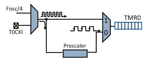
These internal peripherals of the PIC Microcontroller, known as Timers, are pulse counters inside our devices, which allow us to "count" how much time is required to carry out a task or simply to execute a function when a certain time is met. specific time.
The pulses that are entered into these counters can come from the clock (Crystal Oscillator) of the PIC microcontroller or from external sources, which may well be a button or another built-in clock, which would be connected to pins RA4 (For Timer0 ) or to RC0 (For Timer1).
Shoutout to skills.microchip.com
Now, the number of pulses that the timers can count is limited, counting up to 256 pulses for Timer0 of the PIC16F877A and up to 65536 in Timer1.
The number of pulses required usually follows modifications of the following formula
Delay = Pulses * T
Where T is the period, which is obtained from the input frequency as follows:
T =    1
   ---------
   Frequency
Thus, if we want to obtain the number of pulses required for a time that we specify:
Pulses =  Delay
         -------
            T
However, a problem arises from here. If, for example, we wanted to wait 1 second before performing a specific task and our microcontroller's clock was 20MHz, we would have the following result:
Delay = 1 sec

  T =   1
     -------
      20MHz

T = 0.05x10^-6 or 0.05uSec

Pulses =       1
          ------------
           0.05x10^-6

Pulses = 20,000,000.
As we know, 20 million far exceeds the number of pulses that our Timer can count. This is why a frequency divider is used, which we know as a prescaler, which allows us to "slow down" the signal produced by the clock, so that the specific time can be counted with pulses that the timer can handle.
Now, generally, we have 8-bit timers, which are those that can handle 256 pulses (8 bits means that the maximum number it can reach is 11111111 = 255), and 16-bit timers, which handle 65536 pulses (1111111111111111 = 65535), which means that according to the time value we want, we select a different one.
For the PIC16F877A microcontroller we have 3 timers:
- Timer0
- Timer1
- Timer2
For this article we will see Timer0), so that we can understand how it works and in which cases we can use it.
Without further ado, let's look at our Timers.
Timer 0
Shoutout to microdigisoft.com
As we explained in the previous section, Timer0 is an 8-bit timer, which allows us to count up to 256 pulses before executing the interrupt function.
This Timer can be used as both a counter and a timer, depending on the mode we establish in the code.
If we use it as a timer, in order to know what value of pulses we must introduce to Timer0, we solve the following equation:
T = Time_CM * Prescaler(256 - Load_TMR0)
Where CM_Time refers to the time it takes to execute a machine cycle. A machine cycle is a basic microcontroller operation (Ex: Search a memory location), which usually uses 4 pulses of the microcontroller clock.
If we want to calculate the specific time it takes to perform a machine cycle, we use the following equation:
Tcm =     4
        ------
         Fosc
Where Fosc is the frequency at which the microcontroller is working. Now, by clearing Load_TMR0, which is the value we want:
Load_TMR0 = 256 -         (T)
                   -----------------
                    Prescaler * Tcm
And by replacing Tcm with the value of the formula described above:
Load_TMR0 = 256 -    T * Fosc
                  ----------------
                   4 * Prescaler
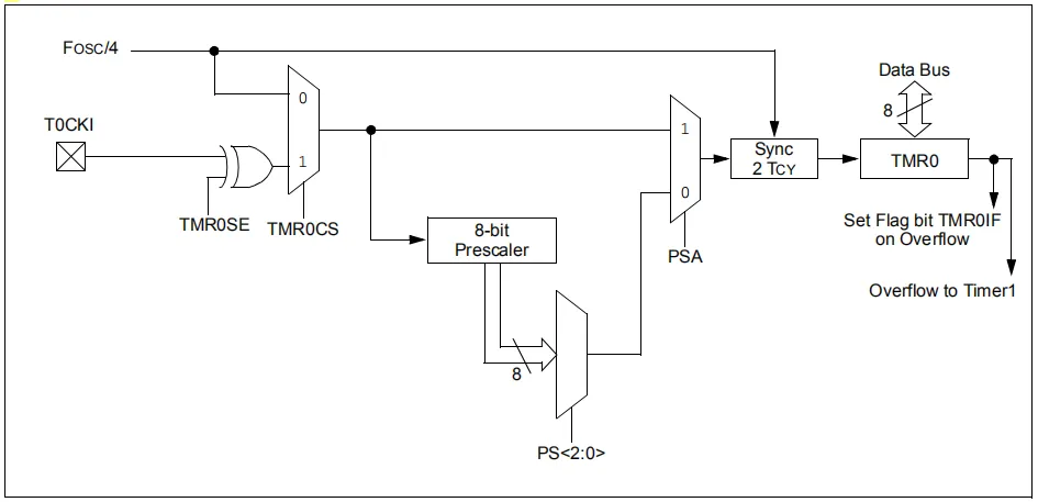
Now, before starting to calculate values, we must select a Prescaler for our Timer0. This Timer has 8 different prescalers, which are 2, 4, 8, 16, 32, 64, 128 and 256, using whichever suits us best for the speed of the pulses and the precision we want.
In our case, we will use a 256 prescaler for our oscillator frequency which will be 20MHz (20x10^6).
Now, as a practical case, let's calculate the value of pulses that we must add to the TMR0 if we want the microcontroller to take 1ms to execute an interrupt (That is, we want the period T to last 1ms).
Substituting the values into the last equation:
Load_TMR0 = 256 - 1x10^-3 * 20x10^6
                 -------------------
                       4*256

Load_TMR0 = 236.47
So we would add this value to our TMR0, but how do we do it? Let's see it in the next section: The code:
Note: The maximum time value that the TMR0 can handle is 13ms, so if you want to perform interrupts with higher time values, it is recommended to use the TMR1 which can support up to 104ms.
The code
Now that we know how the calculations are carried out for the pulse values that are entered into the TMR0, we only have to know the instructions to carry out these operations.
Since they are interruptions, we will use the enable_interrupts command again, only now, instead of using INT_EXT, we will use INT_TIMER0, a value that will also go in the interrupt function label.
enable_interrupts(INT_TIMER0); In addition to enable_interrupts(GLOBAL)

#INT_TIMER0
void interrupt_funct()
{

}
However, another thing that is added to the main program will be the use of two instructions, which are:
- setup_timer_0: This allows us to configure the parameters of Timer0 such as the value of the prescaler and whether it is going to be used as a timer or Counter.
- set_timer0: This is where we enter the value of the pulses that will be executed before the interruption (Load_TMR0, which we calculated earlier)
Now, the setup_timer_0, in order to choose the prescaler and the mode, uses different parameters. For the mode, we can find:
- RTCC_INTERNAL: With this we define the source of the pulses that arrive at timer0 as the internal clock of the PIC, defining it as a timer.
- RTCC_L_TO_H: Here we define the source of the pulses as external, each pulse being sent when the input (RA0) has a rising edge, that is, it changes from low to high.
- RTCC_H_TO_L: In the same way, the source is defined as external, only now the pulses are sent when the state changes from low to high (falling edge).
- RTCC_8_BIT: Some microcontrollers have the option of being able to select whether TIMER0 is used as an 8-bit or 16-bit timer, using this parameter. In the case of the PIC16F877A, it only works as an 8-bit timer.
- RTCC_16_BIT: If the PIC has the option to select TIMER0 as a 16-bit timer, it does just this.
And to select whether the prescaler will be 2,4,8,16,32,64,128 or 256, we use the RTCC_DIV_XX instruction, where we only have to replace XX with the number we want to use.
For example, we will use Timer0 as a Timer with the PIC clock and a prescaler of 256:
setup_timer_0(RTCC_INTERNAL | RTCC_DIV_256)
And if we want to add the value of 236 that we calculate for a waiting time of 1ms between interruptions: We use:
set_timer0(236)
And in this way, we will be ready to create a program for our microcontroller.
Creating the Program
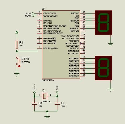
The first thing we will observe when creating our program will be the connections to be made. In this case, we will compare the accuracy of Timer0 when using two 7-segment displays, one whose value will be increased by an interrupt and another by conventional methods in the main program.
In this case, we will use port B for the first display, occupying pins RB0 to RB6. For port D, we will use RD0 to RD6.
As for the program code, the first thing we will do is establish the interrupt function:
#include <16f877a.h>
#fuses HS, NOWDT, NOPROTECT, NOPUT, NOLVP, BROWNOUT
#use delay(clock=20M)
#use fast_io(B)
#use fast_io(D)

long counter = 0;
int display_counter2 = 0;
int display_count = 0;
int display[10] = {0x3F, 0x06, 0x5B, 0x4F, 0x66, 0x6D, 0x7D, 0x07, 0x7F, 0x6F};

#INT_TIMER0
void timer2_interrupt()
{
       counter++;
       output_b(display[display_counter]);
       if(count == 1000)
       {
          counter_display++;

          if(display_count > 9)
          {
             display_count = 0;
             output_b(display[display_counter]);
          }
          counter = 0;
       }
       set_timer0(236);
}
For the start labels, nothing changes from previous editions, using fast_io to define ports B and D as outputs with the simple use of set_tris_b and set_tris_c in the void main.
After this, we will create the variables that we are going to use. In this case we have:
- counter: This will be the counter that will increase for every 1ms (when the interruption occurs), and once it reaches a thousand, it will increase the display value.
- counter_display and counter_display2: These are the variables that range from 0 to 9 to represent the value of each 7-segment display.
- display: This is the arrangement that saves the values that will be represented on the display, which will be accessed with the display counters.
Now, we have to create the interrupt function, to which we now label INT_TIMER0, while the name of this function can be anything.
What this function will do is that when the scheduled 1ms expires, it will increase the value of the first counter while showing the value of the display array in the position with the value of counter_display.
Ex: If display_counter is 1, then output_b(display[display_counter]) will cause the display to show the display value in position 1, which would be 1.
Then, once 1000ms (1 second) has passed and 1000 interrupt functions have been executed, a conditional will allow the counter for the display to increment, eventually setting the counter to 0 so that the count is repeated every second.
However, since we only have numbers from 0 to 9, once the display_counter exceeds the number, the display counter will be reset and the new value will be shown.
A very important aspect that we must remember is to use set_timer0 at the end of this function, to be able to tell timer0 how much value it will have to wait to execute the next interruption, which in this case will be another millisecond.
Now for the main program:
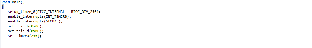
void main()
{
    setup_timer_0(RTCC_INTERNAL | RTCC_DIV_256);
    enable_interrupts(INT_TIMER0);
    enable_interrupts(GLOBAL);
    set_tris_b(0x00);
    set_tris_d(0x00);
    set_timer0(236);


    while(TRUE)
    {
       for(display_count2 = 0; display_count2 < 9; display_count2++)
       {
          output_d(display[display_count2]);
          delay_ms(1000);
       }
    }
}
Here, we will configure the timer with setup_timer_0 according to the mode and prescaler that we will use in this situation (Timer0 as timer and with prescaler of 256).
Then we activate interrupts with TIMER0 (INT_TIMER0) and global interrupts so that the use of interrupts is activated.
Finally, after configuring the pins of port b and d as outputs with set_tris_b and set_tris_d, we enter the load value of timer0 so that the first interrupt can be executed.
Once inside the while loop, we will simply use a for loop that goes from 0 to 9 using counter_display2 as the counter variable, where we will show on the display the value of the array in the position described by the counter, followed by a delay of 1 second.
After configuring all this, if we execute we will see the following:
Here, we can notice that the time in which the sequence of both LEDs increases is slightly different. This difference only increases over time, with at one point it even taking twice as long to change with the interruption than in the standard way.
This is because when calculating the load value we obtained a value of 236.47, however, our IDE only accepts integers when entering, so by omitting the 0.47, the exact precision of the calculation is lost, creating the differences weather.
In this way, we can check two things:
- That it is possible to execute other functions outside the main program on our microcontroller.
- That Timers tend to be imprecise when carrying out time counts.
And above all: We already know how to create programs for interruptions with our Timer0.
I hope this article has been helpful to you, revealing more and more of the mystery of interruptions, where soon we will take a look at Timer1 and Timer0.
I thank you with all my heart for the support you have given me in this last year and I just want to be able to continue providing you with quality content.
Many successes for 2024, and above all:
Full Program
#include <16f877a.h>
#fuses HS, NOWDT, NOPROTECT, NOPUT, NOLVP, BROWNOUT
#use delay(clock=20M)
#use fast_io(B)
#use fast_io(D)

long contador = 0;
int contador_display2 = 0;
int contador_display = 0;
int display[10] = {0x3F, 0x06, 0x5B, 0x4F, 0x66, 0x6D, 0x7D, 0x07, 0x7F, 0x6F};

#INT_TIMER0
void timer2_interrupcion()
{
      contador++;
      output_b(display[contador_display]);
      if(contador == 1000)
      {
         contador_display++;

         if(contador_display > 9)
         {
            contador_display = 0;
            output_b(display[contador_display]);
         }
         contador = 0;
      }
      set_timer0(236);
}

void main()
{
   setup_timer_0(RTCC_INTERNAL | RTCC_DIV_256);
   enable_interrupts(INT_TIMER0);
   enable_interrupts(GLOBAL);
   set_tris_b(0x00);
   set_tris_d(0x00);
   set_timer0(236);


   while(TRUE)
   {
      for(contador_display2 = 0; contador_display2 < 9; contador_display2++)
      {
         output_d(display[contador_display2]);
         delay_ms(1000);
      }
   }
}

Usando los Timers
Shoutout to PIC Microcontrollers
En este artículo encontrarás:
- Introducción
- ¿Qué son los Timers?
- Timer 0
- El código
- Creando el Programa
¡Un saludo a todos y Feliz Año Nuevo!
En la edición previa hablamos sobre las interrupciones, unas subrutinas que se ejecutan cuando cierta condición se cumple, y que nos permiten interrumpir el código principal para realizar otras operaciones, volviendo finalmente a la dirección desde donde se llamaron cuando se terminan.
Sin embargo, solo vimos las interrupciones externas, que solo representan un pequeño porcentaje de las funciones de interrupción que puede llevar a cabo el PIC.
En este caso, veremos otro tipo de interrupciones, las cuales son usadas en su mayoría para generar frecuencias o contadores, las Interrupciones en Timers, que usan las características de estos periféricos internos para llevar su funcionamiento a cabo.
De esta forma, si quieres aprender a como crear interrupcioens con el uso de los Timers, sigue leyendo.
¿Qué son los Timers?
Shoutout to Explore Embedded
Estos periféricos internos del Microcontrolador PIC, conocidos como Timers, son unos contadores de pulsos en el interior de nuestros dispositivos, los cuales nos permiten "contar" cuanto tiempo se requiere para llevar a cabo una tarea o simplemente para ejecutar una función cuando se cumple un tiempo específico.
Los pulsos que se ingresan a estos contadores pueden venir desde el reloj (Oscilador de Cristal) propio del microcontrolador PIC o de fuentes externas, que bien pueden ser un botón u otro reloj incorporado, los cuales irían conectados a los pines RA4 (Para el Timer0) o al RC0 (Para el Timer1).
Shoutout to skills.microchip.com
Ahora bien, la cantidad de pulsos que pueden contar los timers es limitada, contando hasta 256 pulsos para el Timer0 del PIC16F877A y hasta 65536 en el Timer1.
La cantidad de pulsos requerida suele seguir modificaciones de la siguiente fórmula
Delay = Pulsos * T
Donde T es el período, que se obtiene de la frecuencia de entrada de la siguiente manera:
T =   1
    -----
    Freq
Así, si queremos obtener la cantidad de pulsos requerida para un tiempo que específiquemos:
Pulsos = Delay
        -------
           T
Sin embargo, de aquí surge una problemática. Si por ejemplo, quisieramos esperar 1 segundo antes de realizar una tarea específica y el reloj de nuestro microcontrolador fuera de 20MHz, tendríamos el siguiente resultado:
Delay = 1 seg

T =    1
    -------
     20MHz

T = 0.05x10^-6 o 0.05uSeg

Pulsos =      1
         -----------
         0,05x10^-6

Pulsos = 20,000,000.
Como sabemos, 20 millones supera por mucho la cantidad de pulsos que puede contar nuestro Timer. Es por esto, que se usa un divisor de frecuencia el cual conocemos como prescaler, que nos permite "ralentizar" la señal producida por el reloj, de forma que se puedan contar el tiempo específico con pulsos que puede manejar el timer.
Ahora bien, por lo general, tenemos timers de 8 bits, que son los que pueden manejar 256 pulsos (8 bits significa que el número máximo que puede alcanzar es 11111111 = 255), y los de 16, que manejan 65536 pulsos (1111111111111111 = 65535), lo que significa a que de acuerdo al valor de tiempo que queramos, seleccionamos uno distinto.
Para el microcontrolador PIC16F877A tenemos 3 timers:
- El Timer0
- El Timer1
- El Timer2
Para este artículo veremos el Timer0), de forma que podamos entender su funcionamiento y en que casos podemos usarlo.
Sin más que decir, veamos nuestros Timers.
Timer 0
Shoutout to microdigisoft.com
Como explicamos en la sección previa, el Timer0 es un timer de 8 bits, con lo que nos permite contar hasta 256 pulsos antes de ejecutar la función de interrupción.
Este Timer puede ser usado tanto como contador como timer, dependiendo todo del modo que establezcamos en el código.
Si lo usamos como timer, en orden de saber cual es el valor de pulsos que debemos de introducir al Timer0, realizamos un despeje de la siguiente ecuación:
T = Tiempo_CM * Prescaler(256 - Carga_TMR0)
Donde Tiempo_CM se refiere al tiempo que se tarda en ejecutar un ciclo de máquina. Un ciclo de máquina es una operación básica del microcontrolador (Ej: Buscar una posición de memoria), la cual suele usar 4 pulsos del reloj del microcontrolador.
Si queremos calcular el tiempo específico que se tarda en realizar un ciclo máquina, usamos la siguiente ecuación:
Tcm =    4
       ------
        Fosc
Donde Fosc es la frecuencia a la que está trabajando el microcontrolador. Ahora, al despejar Carga_TMR0, que es el valor que queremos:
Carga_TMR0 = 256 -    (  T  )
                   -----------------
                   Prescaler * Tcm
Y al reemplazar Tcm por el valor de la fórmula descrita anteriormente:
Carga_TMR0 = 256 -     T * Fosc
                   ----------------
                     4 * Prescaler
Ahora, antes de comenzar a calcular valores, debemos de seleccionar un Prescaler para nuestro Timer0. Este Timer tiene 8 prescaler distintos, los cuales son de 2, 4, 8, 16, 32, 64, 128 y 256, usando cual nos convenga más para la velocidad de los pulsos y la precisión que queremos.
En nuestro caso, usaremos un prescaler de 256 para nuestra frecuencia de oscilador que será de 20MHz (20x10^6).
Ahora, como un caso práctico, calculemos el valor de pulsos que debemos de agregar al TMR0 si queremos que el microcontrolador tarde 1ms en ejecutar una interrupción (Es decir, queremos que el período T dure 1ms).
Reemplazando los valores en la última ecuación:
Carga_TMR0 = 256 - 1x10^-3 * 20x10^6
                  -------------------
                       4 * 256

Carga_TMR0 = 236.47
Con lo que añadiríamos este valor a nuestro TMR0, pero ¿Cómo lo hacemos? Veamoslo en la siguiente sección: El código:
Nota: El valor máximo de tiempo que puede manejar el TMR0 es de 13ms, por lo que si se desean realizar interrupciones con valores de tiempo más altos, se recomienda usar el TMR1 que puede soportar hasta 104ms.
El código
Ahora que sabemos como se realizan los cálculos para los valores de pulsos que se introducen al TMR0, solo tenemos que conocer las instrucciones para llevar estas operaciones a cabo.
Al ser interrupciones, volveremos a usar el comando enable_interrupts, solo que ahora, en vez de usar INT_EXT, usaremos INT_TIMER0, valor que de igual forma irá en la etiqueta de la función de interrupción.
enable_interrupts(INT_TIMER0); Además del enable_interrupts(GLOBAL)

#INT_TIMER0
void interrupt_funct()
{

}
Sin embargo, otra de las cosas que se añade en el programa principal será el uso de dos instrucciones, las cuales son:
- setup_timer_0: Este nos permite configurar los parámetros del Timer0 como el valor del prescaler y si se va a usar como temporizador o Counter.
- set_timer0: Es aquí donde ingresamos el valor de los pulsos que se ejecutarán antes de la interrupción (Carga_TMR0, que calculamos anteriormente)
Ahora bien, el setup_timer_0, en orden de escoger el prescaler y el modo, usa distintos parámetros. Para el modo, podemos encontrar:
- RTCC_INTERNAL: Con este definimos la fuente de los pulsos que llegan al timer0 como el reloj interno del PIC, definiéndolo como un timer.
- RTCC_L_TO_H: Aquí definimos a la fuente de los pulsos como externa, enviándose cada pulso cuando la entrada (RA0) tenga un flanco de subida, es decir, que cambie de bajo a alto.
- RTCC_H_TO_L: De igual forma se define la fuente como externa, solo que ahora los pulsos se envían cuando se cambia el estado de bajo a alto (Flanco de bajada).
- RTCC_8_BIT: Algunos microcontroladores tienen la opción de poder seleccionar si el TIMER0 se usa como un timer de 8 bits o 16 bits, usando este parámetro. En el caso del PIC16F877A, este solo funciona como timer de 8 bits.
- RTCC_16_BIT: Si el PIC tiene la opción de seleccionar el TIMER0 como un timer de 16 bits, hace justamente esto.
Y para seleccionar si el prescaler será de 2,4,8,16,32,64,128 o 256, usamos la instrucción RTCC_DIV_XX, donde solo tenemos que reemplazar a XX por el número que deseemos usar.
Por ejemplo, usaremos al Timer0 como un Timer con el reloj del PIC y un prescaler de 256:
setup_timer_0(RTCC_INTERNAL | RTCC_DIV_256)
Y si queremos añadir el valor de 236 que calculamos para un tiempo de espera de 1ms entre interrupción: Usamos:
set_timer0(236)
Y de esta forma, ya estaremos preparados para crear un programa para nuestro microcontrolador.
Creando el Programa
Lo primero que observaremos al crear nuestro programa serán las conexiones a realizar. En este caso, compararemos la precisión del Timer0 al usar dos displays de 7 segmentos, uno cuyo valor será aumentado por una interrupción y otro por métodos convencionales en el programa principal.
En este caso, usaremos el puerto B para el primer display, ocupando los pines del RB0 al RB6. Para el puerto D, usaremos del RD0 al RD6.
En cuanto al código del programa, lo primero que haremos será establecer la función de interrupción:
#include <16f877a.h>
#fuses HS, NOWDT, NOPROTECT, NOPUT, NOLVP, BROWNOUT
#use delay(clock=20M)
#use fast_io(B)
#use fast_io(D)

long contador = 0;
int contador_display2 = 0;
int contador_display = 0;
int display[10] = {0x3F, 0x06, 0x5B, 0x4F, 0x66, 0x6D, 0x7D, 0x07, 0x7F, 0x6F};

#INT_TIMER0
void timer2_interrupcion()
{
      contador++;
      output_b(display[contador_display]);
      if(contador == 1000)
      {
         contador_display++;

         if(contador_display > 9)
         {
            contador_display = 0;
            output_b(display[contador_display]);
         }
         contador = 0;
      }
      set_timer0(236);
}
Para las etiquetas del inicio, nada cambia respecto a ediciones anteriores, usando fast_io para definir a los puertos B y D como salidas con el simple uso de set_tris_b y set_tris_c en el void main.
Después de esto, crearemos las variables que vamos a usar. En este caso tenemos:
- contador: Este será el contador que aumentará por cada 1ms (Cuando ocurra la interrupción), y que una vez que llegue a mil, hará que aumente el valor del display.
- contador_display y contador_display2: Estas son las variables que van del 0 al 9 para representar el valor de cada display de 7 segmentos.
- display: Este es el arreglo que guarda los valores que se representarán en el display, a los que se accederá con los contadores de display.
Ahora, nos toca crear la función de interrupción, a la que ahora colocamos la etiqueta de INT_TIMER0, mientras que el nombre de esta función puede ser cualquiera.
Lo que hará esta función es que al cumplirse los 1ms pautados, nos aumentará el valor del primer contador mientras que muestra el valor del arreglo display en la posición con el valor de contador_display.
Ej: Si contador_display es 1, entonces output_b(display[contador_display]) hará que en el display se muestre el valor de display en la posición 1, que sería 1.
Luego, una vez que transcurran 1000ms (1 segundo) y se hayan ejecutado 1000 funciones de interrupción, un condicional permitirá que el contador para el display aumente, colocando finalmente el contador a 0 para que se repita el conteo cada segundo.
Sin embargo, ya que solo tenemos números del 0 al 9, una vez que contador_display supere al número, se reseteara el contador del display y se mostrará el nuevo valor.
Un aspecto muy importante que debemos de recordar es el de usar el set_timer0 al final de esta función, para poder indicarle al timer0 cuanto es el valor que tendrá que esperar para ejecutar la siguiente interrupción, que en este caso será otro milisegundo.
Ahora, para el programa principal:
void main()
{
   setup_timer_0(RTCC_INTERNAL | RTCC_DIV_256);
   enable_interrupts(INT_TIMER0);
   enable_interrupts(GLOBAL);
   set_tris_b(0x00);
   set_tris_d(0x00);
   set_timer0(236);


   while(TRUE)
   {
      for(contador_display2 = 0; contador_display2 < 9; contador_display2++)
      {
         output_d(display[contador_display2]);
         delay_ms(1000);
      }
   }
}
Aquí, configuraremos el timer con setup_timer_0 de acuerdo al modo y al prescaler que usaremos en esta situación (Timer0 como timer y con prescaler de 256).
Luego, activamos las interrupciones con TIMER0 (INT_TIMER0) y las interrupciones globales para que se active el uso de interrupciones.
Finalmente, tras configurar a los pines del puerto b y d como salidas con set_tris_b y set_tris_d, ingresamos el valor de la carga del timer0 para que se pueda ejecutar la primera interrupción.
Una vez dentro del ciclo while, simplemente usaremos un ciclo for que vaya del 0 al 9 usando como variable contador al contador_display2, donde mostraremos en el display el valor del arreglo en la posición descrita por el contador, seguida por un delay de 1 segundo.
Tras configurar todo esto, si ejecutamos observaremos lo siguiente:
Aquí, podemos notar que el tiempo en que aumenta la secuencia de ambos leds es ligeramente distinto. Esta diferencia no hace sino aumentar con el tiempo, teniendo que en un punto incluso se tarda el doble el cambiar con la interrupción que de forma estándar.
Esto se debe a que al calcular el valor de la carga obtuvimos un valor de 236.47, más sin embargo, nuestro IDE solo acepta números enteros al ingresar, por lo que al omitir el 0.47, se pierde la precisión exacta del cálculo, creando las diferencias del tiempo.
De esta forma, podemos comprobar dos cosas:
- Que es posible ejecutar otras funciones fuera del programa principal en nuestro microcontrolador.
- Que los Timers tienden a ser imprecisos a la hora de llevar a cabo conteos de tiempo.
Y sobre todo: Ya sabemos como crear programas para interrupciones con nuestro Timer0.
Espero que este artículo les haya servido de ayuda, desvelando cada vez más el misterio de las interrupciones, donde proximamente echaremos un vistazo al Timer1 y al Timer0.
Les agradezco de todo corazón el apoyo que me han brindado en este último año y solo quiero poder seguir brindándoles contenido de calidad.
Muchos exitos para este 2024, y por sobre todo:
Programa Completo
#include <16f877a.h>
#fuses HS, NOWDT, NOPROTECT, NOPUT, NOLVP, BROWNOUT
#use delay(clock=20M)
#use fast_io(B)
#use fast_io(D)

long contador = 0;
int contador_display2 = 0;
int contador_display = 0;
int display[10] = {0x3F, 0x06, 0x5B, 0x4F, 0x66, 0x6D, 0x7D, 0x07, 0x7F, 0x6F};

#INT_TIMER0
void timer2_interrupcion()
{
      contador++;
      output_b(display[contador_display]);
      if(contador == 1000)
      {
         contador_display++;

         if(contador_display > 9)
         {
            contador_display = 0;
            output_b(display[contador_display]);
         }
         contador = 0;
      }
      set_timer0(236);
}

void main()
{
   setup_timer_0(RTCC_INTERNAL | RTCC_DIV_256);
   enable_interrupts(INT_TIMER0);
   enable_interrupts(GLOBAL);
   set_tris_b(0x00);
   set_tris_d(0x00);
   set_timer0(236);


   while(TRUE)
   {
      for(contador_display2 = 0; contador_display2 < 9; contador_display2++)
      {
         output_d(display[contador_display2]);
         delay_ms(1000);
      }
   }
}
Comments