Controlling SCR WITH PIC16F877A ES/EN
5 comments
After having studied such an old gadget as the SCR I thought it would be interesting to find a way to control it using a microcontroller to see how much we can improve its performance.
This is one of those simple but effective articles, so much so that I am excited to give you something like this because I am sure it will be very easy to understand, plus I have accumulated enough images that validate the process, I hope you like it as much as I have liked it.
Luego de haber estudiado un artilugio tan antiguo como lo es el SCR me ha parecido interesante buscar una forma de controlarlo usando un microcontrolador para comprobar cuanto podemos mejorar su rendimiento.
Este es uno de esos artículos simples pero efectivo, tanto que estoy emocionado de entregarles algo asi porque estoy seguro que sera muy facil entenderlo, además he acumulado suficientes imágenes que validan el proceso, espero que les guste tanto como me ha gustado a mi.
Electronic circuit |
|---|
If you have not read the article Component Electronics: The SCR EN/ES I advise you to stop for a moment and go there because it contains information that will not be explained again in this article, those are a little more theoretical, here we are at the second level 😎.
When we control an SCR with a potentiometer taking the power signal as a trigger signal we can only control 90 degrees, the advantage is that being the same source both voltages are always in phase.
If we can successfully implement a trigger signal from the microcontroller we can control the full half cycle (180) and also trigger at any angle very accurately, trigger under any criteria or condition we need and manage the output power at will.
The main problem and perhaps the only one would be to achieve that the microcontroller can detect the behavior of the voltage at the source at all times, so it can determine at what angle it is and if it is convenient or not to send the trigger.
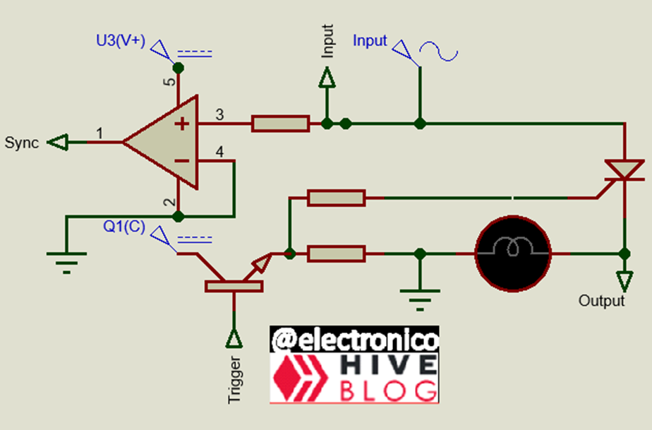
But every article I write has a purpose, so let's take the Zero crossing detector EN/ES out of the repertoire, we will take a portion of the source voltage across a resistor high enough to protect the operational amplifier and produce a 5VDC output when it crosses zero into the positive half-cycle.
Si no has leido el articulo Component Electronics: The SCR EN/ES te aconsejo que te detengas por un momento y vayas alla porque contiene informacion que no se volvera a explicar en este articulo, aquellos es un poco mas teorico, aqui estamos en el segundo nivel 😎.
Cuando controlamos un SCR con un potenciómetro tomando la señal de potencia como señal de disparo únicamente podemos controlar 90 grados, la ventaja es que al ser la misma fuente ambas tensiones están siempre en fase.
Si logramos implementar con éxito una señal de disparo desde el microcontrolador podremos controlar el semiciclo completo (180) y además disparar en cualquier ángulo con mucha precisión, disparar bajo cualquier criterio o condición que necesitemos y manejar la potencia de salida a nuestro antojo.
El problema principal y tal vez el unico seria lograr que el microcontrolador pueda detectar el comportamiento del voltaje en la fuente en todo momento, de esa forma puede determinar en qué ángulo se encuentra y si es conveniente o no enviar el disparo.
Pero cada articulo que escribo tiene un proposito, asi que saquemos del repertorio el Zero crossing detector EN/ES, tomaremos mediante una porcion del voltaje de la fuente a traves de una resistencia lo suficientemente alta para proteger el amplificador operacional y produciremos una salida de 5VDC cuando se cruce el cero hacia el semiciclo positivo.
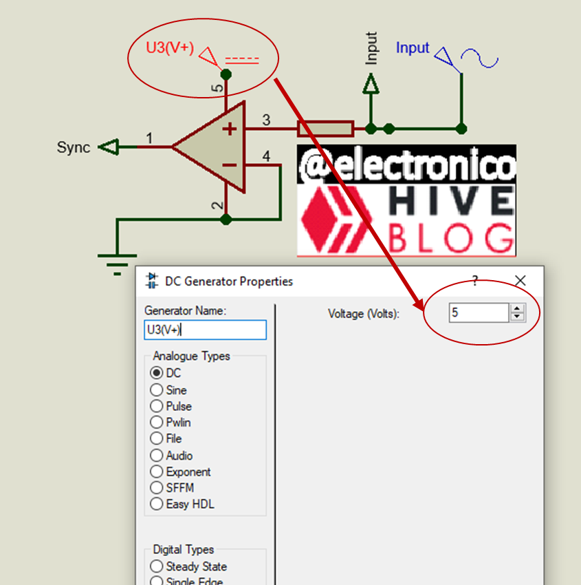
This pulse is held high as long as the positive half-cycle is maintained and can be used as an input signal to the microcontroller to maintain synchronism.
Este pulso se mantiene en alto todo el tiempo que se mantiene el semiciclo positivo y puede ser usado como señal de entrada al microcontrolador para mantener un sincronismo.
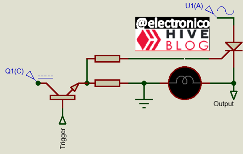
The second step will be to create a circuit capable of receiving the 5VDC coming from the microcontroller as a trigger signal and switch another source to supply the trigger current to the SCR, so the microcontroller will be the one to decide when the SCR is triggered.
El segundo paso será crear un circuito capaz de recibir los 5VDC que provienen del microcontrolador como señal de disparo y conmutar otra fuente que suministre la corriente de disparo al SCR, así el microcontrolador será quien decida cuando se dispara el SCR.
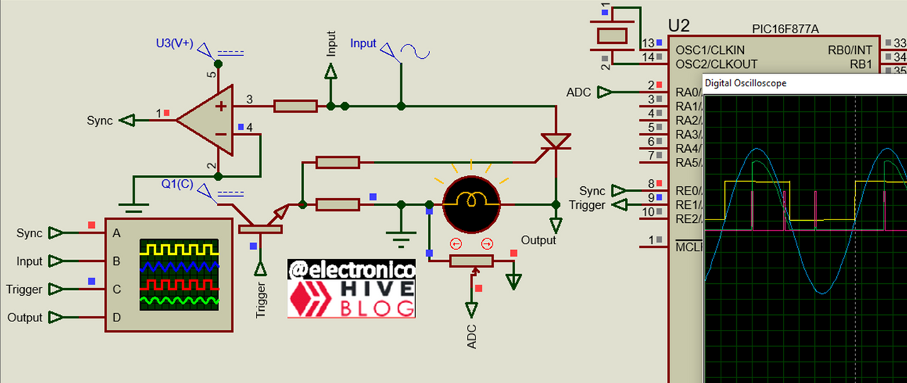
We can arrange the two circuits into one so that our design can take shape:
Podemos acomodar los dos circuitos en uno para que nuestro diseño vaya tomando forma:
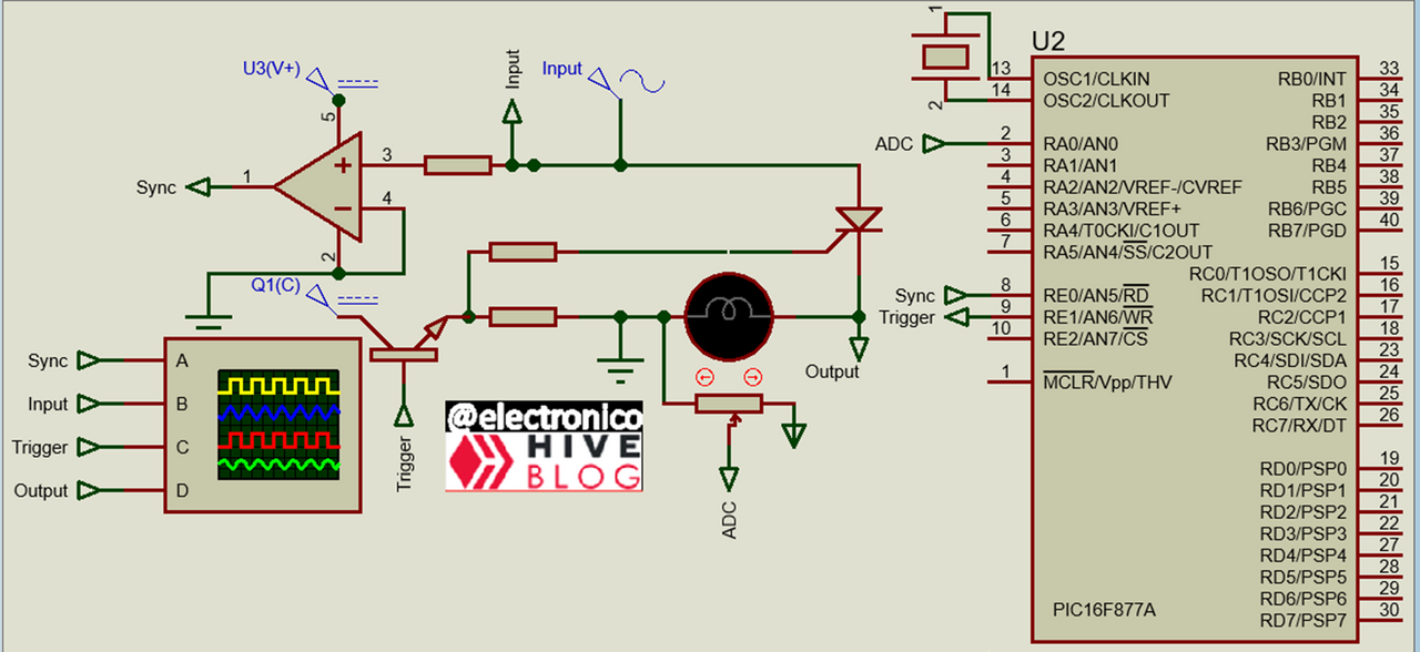
Now we are going to place our microcontroller, we will place a potentiometer as ADC to establish a form of manual control, it is the simplest but not the only one, also we will use the PORT E (Which we have never used before) to receive the sync signal and to send the trigger signal, then we will only use 3 pins of the microcontroller, an ADC input, a discrete input and a discrete output.
Ahora vamos a colocar nuestro microcontrolador, colocaremos un potenciómetro como ADC para establecer una forma de control manual, es la más simple pero no la única, además usaremos el PORT E (Que nunca antes hemos usado) para recibir la señal de sincronismo y para enviar la señal de disparo, entonces solo usaremos 3 pines del microcontrolador, una entrada ADC, una entrada discreta y una salida discreta.
Now we are going to design our program, the first thing to do is to establish the configuration lines and variables:
Ahora vamos a diseñar nuestro programa, lo primero es establecer las líneas de configuración y las variables:
#include <16f877a.h>

#device ADC = 10

#fuses HS,NOWDT,NOPROTECT,NOPUT,NOLVP,BROWNOUT

#use delay(clock=20M)

#use standard_io(E)

#include <map_function.c

long raw_value;

long trigger;

void main()

{

   setup_adc_ports(AN0);

   setup_adc(adc_clock_internal);
The raw_value variable will be used to read the data from the ADC and the trigger variable will be used to control the trigger now let's think for a moment how to make the trigger occur when we want, the first thing we are going to observe is that we are working with time, from the moment the Sync pulse is received until it ends is the time in which a trigger can be sent to produce an output power.
We are using a frequency of 60Hz and that gives us a period of 1/60 = 16.7 ms but remember that in that time a positive and a negative half cycle occurs, so we must divide by 2 which gives 8.33 ms, it means that from the instant the pulse is received until the instant the positive half cycle ends there are 8.33 ms which we can approximate to 8334us (we take it to us for better accuracy).
Now we want an input value in the ADC with a range of 0 to 1023 to produce a proportional output with a range of 8334 to 0 and that output value is stored in the variable trigger, where trigger is the time to wait before producing a trigger, if the ADC is 0 the waiting time will be 8334 which is the duration of the positive half cycle, the trigger will occur in the negative half cycle and there will be no output in the SCR.
La variable raw_value servirá para leer los datos del ADC y la variable trigger servirá para controlar el disparo ahora pensemos por un momento como hacer para que el disparo ocurra cuando queramos, lo primero que vamos a observar es que estamos trabajando con el tiempo, desde el momento en el que se recibe el pulso de Sync hasta que termina es el tiempo en el que se puede enviar un disparo para producir una potencia de salida.
Estamos usando una frecuencia de 60Hz y eso nos da un periodo de 1/60 = 16.7 ms pero recordemos que en ese tiempo ocurre un semiciclo positivo y uno negativo, así que debemos dividir entre 2 lo cual da 8,33 ms, significa que desde el instante en el que se recibe el pulso hasta el instante en que termina el semiciclo positivo hay 8,33 ms que podemos aproximar a 8334us (lo llevamos a us para obtener una mejor precisión).
Ahora queremos que un valor de entrada en el ADC con un rango de 0 a 1023 produzca una salida proporcional con un rango de 8334 a 0 y ese valor de salida lo guardamos en la variable trigger, donde trigger es el tiempo que se debe esperar antes de producir un disparo, si el ADC vale 0 el tiempo de espera será 8334 que es lo que dura el semiciclo positivo, el disparo ocurrirá en el semiciclo negativo y no habrá salida en el SCR.
After the wait established by trigger what we do is to activate the PIN that sends the trigger signal for a certain time and then deactivate it quickly to produce a very fast pulse that allows to activate the SCR and after a very short time to turn off the signal since a small instant is enough to trigger the SCR in the rest of time that remains to the positive half-cycle.
All this we can do with very few lines in a relatively short program to which we are accustomed.
Después de la espera establecida por trigger lo que hacemos es activar el PIN que envía la señal de disparo por un cierto tiempo y luego desactivarlo rápidamente para producir un pulso muy rápido que permita activar el SCR y luego de un tiempo muy corto apagar la señal ya que un pequeño instante es suficiente para disparar el SCR en el resto de tiempo que le quede al semiciclo positivo.
Todo esto lo podemos hacer con muy pocas líneas en un programa relativamente corto a los que estamos acostumbrados.
while(true)

   {

      set_adc_channel(0);

      delay_us(2);

      raw_value = read_adc();

      trigger = map(raw_value, 0, 1023, 8334, 0);

      if(input(PIN_E0) == 1)

      {

       delay_us(trigger);

       output_high(PIN_E1);

       delay_us(200);

       output_low(PIN_E1);

      }

   }

}
It is a simple but functional program, it could be improved but it is a matter of aesthetics and I prefer simplicity if that allows the article to be understood by a greater number of users.
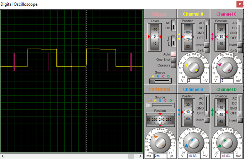
The pulse will be sent whenever the positive half-cycle is present with delays provided by the ADC since this is established by the conditional if that we use, the consequence is that we will have several pulses in the half-cycle, however only the first pulse matters, remember that after the SCR is activated it will ignore the other pulses and will only be deactivated when the source signal is zero.
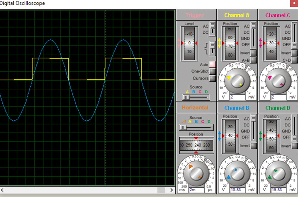
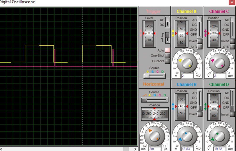
Now let's compare the sync signal with the trigger pulses and see how they increase as we demand a trigger closer to the start of the pulse.
Es un programa sencillo pero funcional, pudiese mejorarse pero ya es un asunto de estética y prefiero la simpleza si eso permite que el artículo sea comprendido por un mayor número de usuarios.
El pulso se enviará siempre que el semiciclo positivo este presente con retardos proporcionados por el ADC ya que así lo establece el condicional if que usamos, la consecuencia es que tendremos varios pulsos en el semiciclo, sin embargo solo importa el primer pulso, recordemos que luego que el SCR se activa ignorara los demás pulsos y solo se desactivará cuando la señal de la fuente sea cero.
Ahora comparemos la señal de sincronismo con los pulsos de disparo y veamos cómo aumentan a medida que exigimos un disparo más cercano al inicio del pulso.
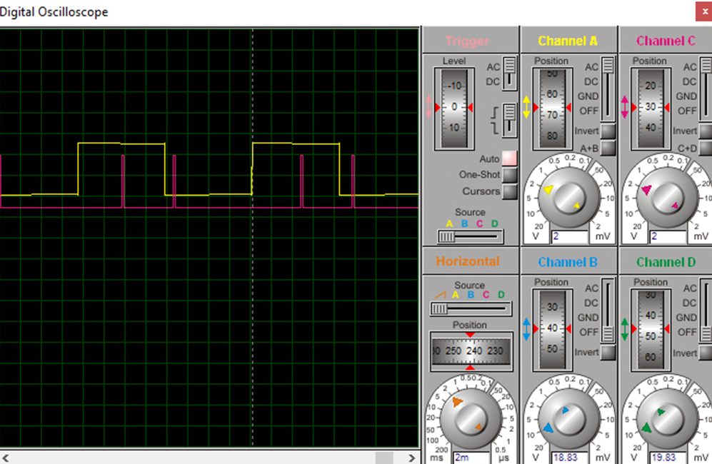
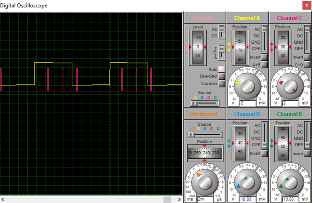
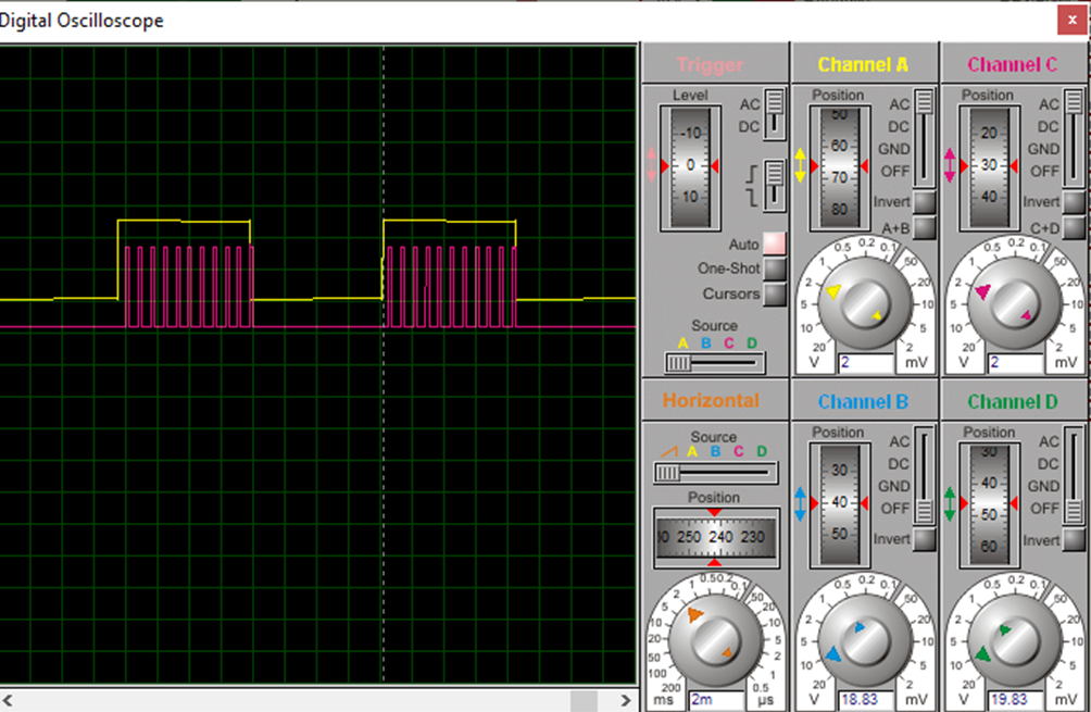
Now let's go to a simulation, we vary the potentiometer (ADC value) and we will see how the pulse (red line) occurs closer to the beginning of the positive half cycle (yellow line) as we increase the value, we will also notice how the SCR output voltage (green line) is affected and we will see that only the first trigger pulse that occurs during a positive half cycle has an effect on it.
Ahora vamos a una simulación, variamos el potenciómetro (Valor del ADC) y veremos como el pulso (linea roja) ocurre más cerca del inicio del semiciclo positivo (linea amarilla) a medida que aumentamos el valor, además notaremos como es afectado el voltaje de salida del SCR (linea verde) y comprobaremos que solo tiene efecto sobre ella el primer pulso de disparo que ocurre durante un semiciclo positivo.
To check the power control that can be established with a trigger between 0 and 180 degrees let's look only at the source voltage and the output voltage of the SCR, especially as the trigger angle varies as we vary the potentiometer, we can also appreciate the effect that occurs in the load (lamp for this case).
Para comprobar el control de potencia que se puede establecer con un disparo entre 0 y 180 grados miremos solo el voltaje de la fuente y el voltaje de salida del SCR, especialmente como el angulo de disparo varia a medida que variamos el potenciómetro, también podemos apreciar el efecto que se produce en la carga (lampara para este caso).
Finally, let's look at the behavior of all the signals together as we vary the ADC.
Para finalizar miremos el comportamiento de todas las señales juntas mientras variamos el ADC.
It has been a pleasure to write for you, I remain attentive to comments on the subject, until next time! 🤗
Ha sido un gusto escribir para ustedes, quedo atento a los comentarios sobre el tema, hasta la próxima! 🤗

Comments